TM 9-2320-302-34
0039 00-11
ACCESSORY DRIVE REPAIR - CONTINUED
0039 00
ASSEMBLY - CONTINUED
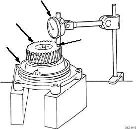
15.
Support accessory drive assembly (1) as shown. Position dial indicator (18) so indicator stem (19) rests on face of acces-
sory drive gear (7) just inboard of accessory drive gear teeth.
NOTE
As accessory drive gear is rotated, dial indicator needle may register to left and right of zero. Total amount
of dial indicator needle movement gives total indicated runout (TIR).
16.
Zero dial indicator (18). Rotate accessory drive gear (7) two full rotation. Allowable TIR is 0.0015 in (0.04 mm).
END OF WORK PACKAGE
2
1
18
7
19