TM 5-2330-325-14&P
4-48.
SLACK ADJUSTER REPLACEMENT (Continued).
(5)
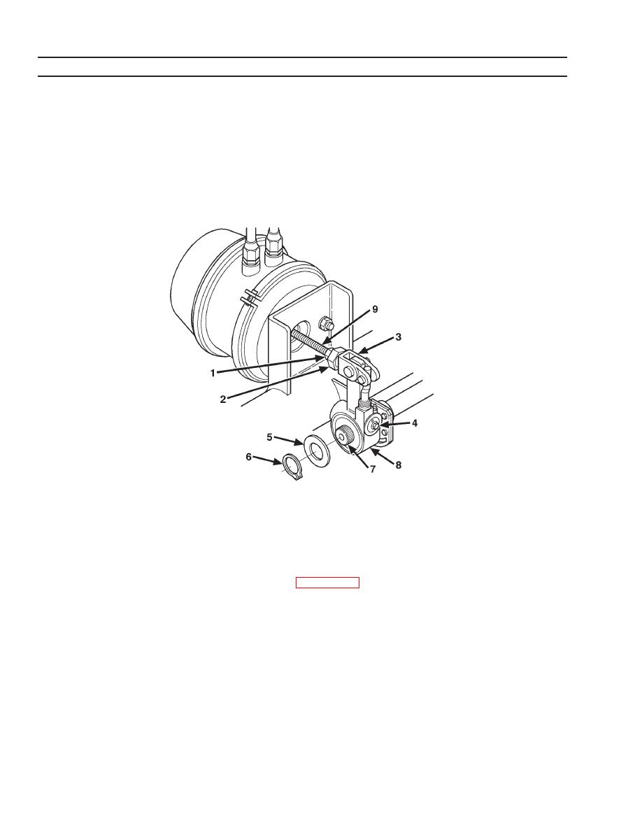
Using adjusting screw (4), align clevis and air chamber shaft.
(6)
Turn 1-1/4 in. slack adjuster nut (2) counterclockwise to thread onto clevis until handtight.
(7)
Apply locktite to threads and tighten jamnut (1).
NOTE
Cotter pin securing slack adjuster to clevis should be installed facing
wheel.
e.
Adjustment.
NOTE
Slack adjusters are self-adjusting. Use this procedure when installing
new slack adjusters or when slack adjusters have been disconnected.
(1)
Place clevis installation gage (12) (Ref. Appendix G) so it fits over the body of the larger
clevis pin (11).
(2)
If slack adjuster is properly adjusted, a pencil can be placed into the center of the
camshaft (7) and the 6.0 in. slack hole (14) of the gage (12). The notch in gage and the
smaller of the clevis pins (13) should also be aligned.
(3)
Adjust the 3/4 in. adjuster nut (10) in or out on the air chamber shaft (9) until the centers of
the 6.0 in. slack hole (14) and the camshaft (7) are aligned.
4-54


