
II106700-7
Rev. -
Page 69
aa. Torque the six locknuts (3/8 16) on top of the driver's-side Roof Panel Front
Attachment Bracket to 23 ft-lb.
ab. Torque the four rear top locknuts (3/8 16) on top of the Rear Roof Panel Rear
Bracket to 23 ft-lb.
ac. Torque the four locknuts (3/8 16) on the bolts going through the Roof Panel Rear
Bracket to 35 ft-lb.
ad. Torque the 12 Roof Armor Panel Attachment bolts (5/16 18 x 1.250 and 1.750 LG)
(on the passenger side) to 13 ft-lb.
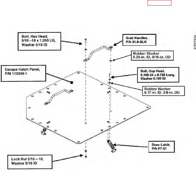
ae. Install two Handles onto the top of the Escape Hatch Panel (see Figure 44)
(P/N 113346-1) using two bolts (5/16 18 x 1.250 LG), four metal washers (5/16 ID),
four rubber washers (0.29 ID, 9/16 OD), and two nuts (5/16 18) for each Handle.
Figure 44. Escape Hatch Handle and Draw Latch illustration.
CAUTION
Do not over-tighten the fasteners. The fasteners may strip the threaded hole in
the Draw Latch Connector if they are over-tightened.