
II106700-5
Rev. B
Page 78
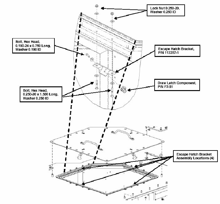
Do not over-tighten the fasteners. They will strip the threaded hole in the
Draw Latch Component if they are over-tightened.
ah. Install the four Bracket Assemblies using the hardware shown, and in the locations
shown, in Figure 46b. Do not fully tighten the bolts at this time.
Figure 48b. Installation of the Escape Hatch Brackets.
ak. Attach the four Escape Hatch Brackets (P/N 113357-1) to the top of the cab
adjacent to the Escape Hatch (four sides) using two bolts (3/16 24 x 1/4 LG) and
two washers (3/16 ID) for each bracket.
am. Install the Escape Hatch in the Roof.