
II106700-5
Rev. B
Page 77
ad. Torque the 12 Roof Armor Panel Attachment bolts (5/16 18 x 1.250 and 1.750 LG)
(on the passenger side) to 13 ft-lb.
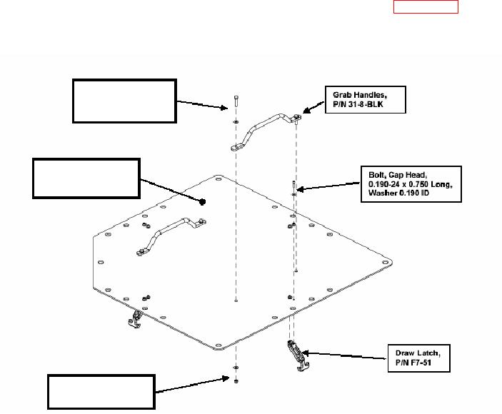
ae. Install two Handles onto the top of the Escape Hatch Panel (see Figure 48A)
(P/N 113346-1) using two bolts (5/16 18 x 1.250 LG), four washers (5/16 ID), and
two nuts (5/16 18) for each Handle.
Bolt, Hex Head,
5/16 18 x 1.250 LG,
Washer 5/16 ID
Escape Hatch Panel,
P/N 113346-1
Lock Nut 5/16 18,
Washer 5/16 ID
Figure 48A. Escape Hatch Handle and Draw Latch illustration.
CAUTION
Do not over-tighten the fasteners. The fasteners may strip the draw latch
connector if they are over-tightened.
af. Install four Draw Latch T-Handles (P/N F7-51) onto the bottom of the Escape Hatch
Panel (P/N 113346-1) using two bolts (3/16 24 x 0.750 LG) and two washers
(3/16 ID) for each latch.
ag. Assemble four Keeper Pins (from the Draw Latch) into the four Escape Hatch
Brackets (P/N 113357-1) with a bolt (3/16 24 x 1/4 LG) and a washer (3/16 ID) for
each bracket.
CAUTION