
II106700-7
Rev. -
Figure 34. Re-install the Tire Carrier.
5. Torque the screws (6) to 80 ft-lb.
6. Stow the Spare Tire (Per TM 9-2320-279-10).
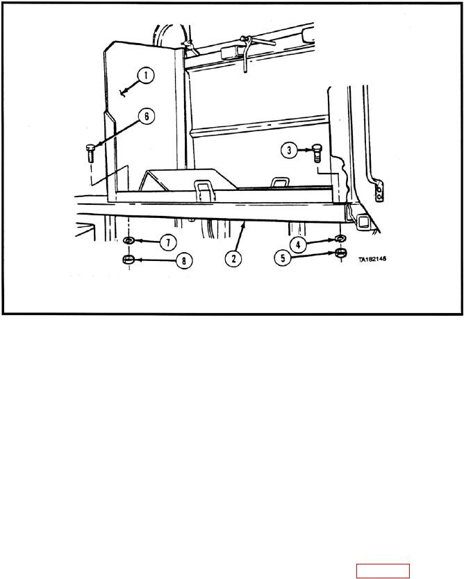
5.1.7 Re-Install the Cab Steps (with the Internal Clearance Light)
a. Apply Loctite 242 to four bolts (5/16 18 x 1.250 LG).
b. Position the hard metal cab step onto the bottom surface of the driver's-side
Blast Deflector using the four previously prepared bolts (5/16 18 x 1.500 LG),
eight washers (5/16 ID), and four locknuts (5/16 18). Torque the locknuts to
18 ft-lb.
5.1.8 Install the Side Armor, Kit P/N 115500-1 (Driver's Side).
a. Install the A-Pillar Bracket (P/N 115503) onto the door pillar of the vehicle using nine
bolts (5/16 18 x 1.500 LG). Torque the bolts to 18 ft-lb (see Figure 35).
b.
Install a lifting strap through the two lifting eyes located at the top corners of the Side
Armor Panel assembly.