
TB 2300-420-20-1
PARKING BRAKE CONTROL ASSEMBLY REPLACEMENT (ONE-PIECE)- Continued
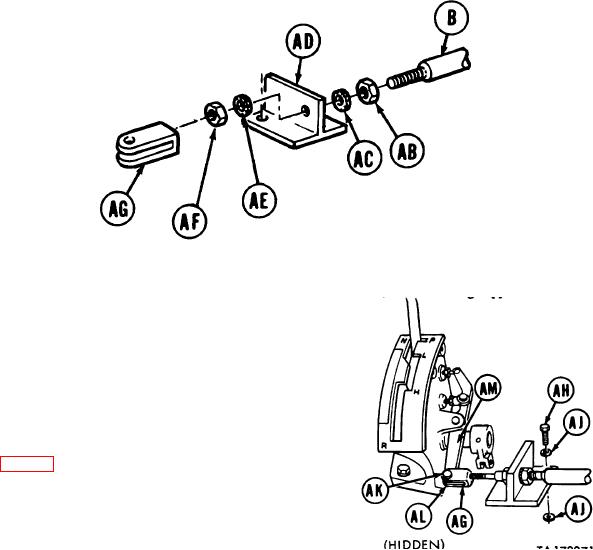
22. At shift lever, using 15/16 inch wrench, install nut
(AB) and lockwasher (AC) on control assembly
(B).
23. Slide control assembly (B) through support
bracket (AD).
24. Using 15/16 inch wrench, install lockwasher (AE)
and nut (AF).
25. Using adjustable wrench, install clevis (AG) 3/8
to 5/8 inch onto shaft.
26. Using 9/16 inch socket and extension, install bracket (AD) to bearing support bracket with two screws (AH) four
washers (AJ).
NOTE
Pin (AK) and new cotter pin (AL)
securing clevis (AG) to lever (AM)
need not be installed until adjustment
procedure is performed.
27. Perform parking brake
control
assembly
adjustment page 9.
TA173271
END OF TASK
33