
TM 5-2330-325-13&P
0048
REMOVAL
1.
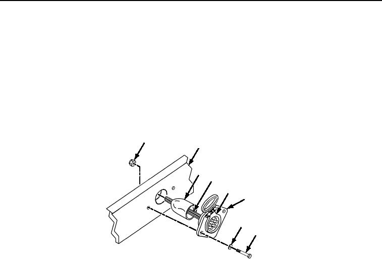
Slide boot (Figure 1, Item 3) off of connector (Figure 1, Item 5) at rear of receptacle (Figure 1, Item 6).
2.
Remove two self-locking nuts (Figure 1, Item 1) from rear of receptacle (Figure 1, Item 6). Discard
self-locking nuts (Figure 1, Item 1).
3.
Turn connector (Figure 1, Item 5) clockwise and remove from receptacle (Figure 1, Item 6).
4.
Tag and disconnect wires (Figure 1, Item 4) from connector (Figure 1, Item 5).
5.
Remove two screws (Figure 1, Item 8), washers (Figure 1, Item 7), and receptacle (Figure 1, Item 6) from
gooseneck (Figure 1, Item 2).
1
2
3
4
5
6
7
8
466-0043
Figure 1.
12-volt Receptacle Replacement.
END OF TASK
INSTALLATION
1.
Install receptacle (Figure 1, Item 6) on gooseneck (Figure 1, Item 2) with two screws (Figure 1, Item 8),
washers (Figure 1, Item 7), and new self-locking nuts (Figure 1, Item 1).
2.
Connect wires (Figure 1, Item 4) to connector (Figure 1, Item 5) as tagged during removal.
3.
Insert connector (Figure 1, Item 5) in receptacle (Figure 1, Item 6) and turn counterclockwise to set.
4.
Slide boot (Figure 1, Item 3) over connector (Figure 1, Item 5).
END OF TASK
FOLLOW ON TASK
Connect power source and test electrical system for proper operation.
END OF TASK
END OF WORK PACKAGE