
TB 2300-420-20-1
PARKING BRAKE CONTROL ASSEMBLY REPLACEMENT (REAR ONLY OF TWO-PIECE)-Continued
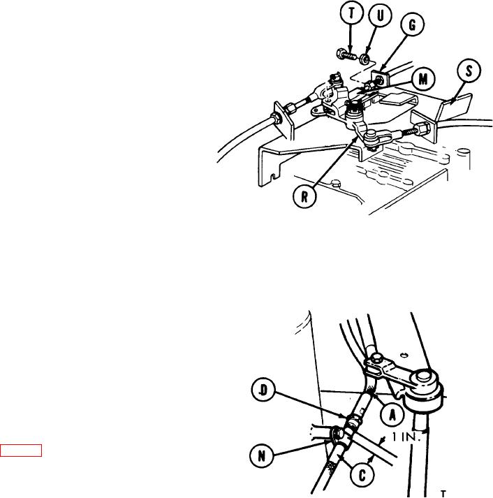
11. Position connector (M) in bellcrank assembly (R). Using a 9/16 inch socket and extension, install bracket (G) to
bracket assembly (S) with two screws (T) and lockwashers (U).
NOTE
Pin and clip securing connector (M)
to bellcrank (R) need not be installed
until
adjustment
procedure
is
performed.
CAUTION
Make sure control assembly (C) is
secured to hull wall with clamp (N)
located on metal casing, 1 inch below
disconnect nut (D).
12. Using adjustable wrench on flats of control assembly (A), and torque wrench with 7/8 inch crowfoot tighten
disconnect nut (D) to 35-50 lb-in (8.9 to 12.7 Nm).
13. Perform parking brake
control
assembly
adjustment (page 9).
TA173287
END OF TASK
49

