
TB 9-2320-279-13&P-4
0024
WARNING
Circuit breakers No. 4, 5, 6, and 10 are always electrically live. Use care when working
around these circuit breakers. Failure to comply may result in injury or death to personnel.
1.
Connect engine harness connector MC20. Refer to schematics.
2.
Connect engine harness connector MC21.
3.
Connect chassis harness connector MC25.
4.
Connect chassis harness connector MC4.
5.
Connect cab harness connector MC5.
6.
Install skid plate grille (refer to TM-9-2320-315-14&P).
7.
Connect cab harness connector MC150.
8.
Connect cab harness connector MC66.
NOTE
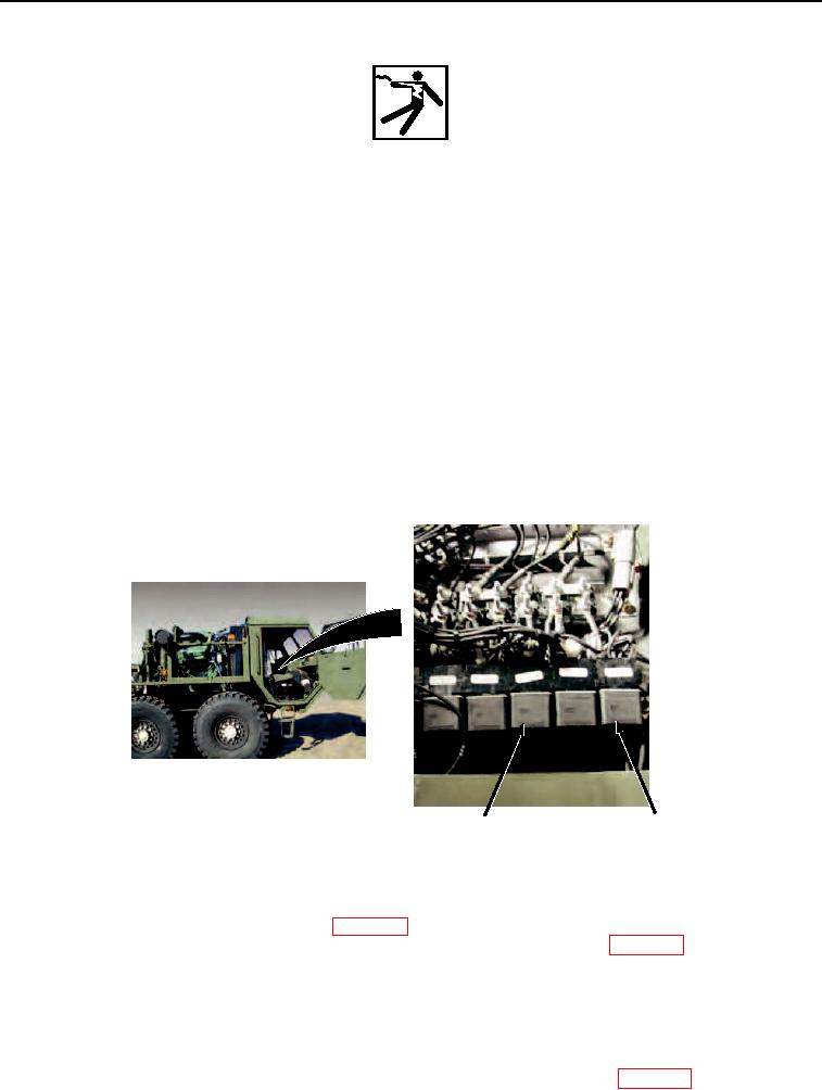
Mark relays before swapping.
9. Swap high idle active relay R10 with backup alarm relay R12 (refer to TM 9232031415&P).
10. Start engine (refer to TM 9-2320-279-10).
RELAY
RELAY
R12
R10
Figure 44.
11. Set PTO ENGAGE switch to ON position. (WP 0015)
12. Set heavy-duty winch control station HIGH IDLE ON/OFF switch to ON position. (WP 0015)
NOTE
Engine high idle speed is 1,500 RPM.
13. Observe engine operation. Inspect tachometer for increase in engine speed.
14. Set heavy-duty winch control station HIGH IDLE ON/OFF switch to OFF position. (WP 0015)