TM 9-2320-363-34-2
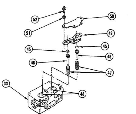
45. INSTALL SEAL RING (45) BETWEEN RAISED LANDS ON UNLOADER PISTON (46).
46. INSTALL UNLOADER SPRING (47) ON OPPOSITE END OF UNLOADER PISTON (46).
47. SUPPORT CYLINDER HEAD (33) ON BENCH, DECK SIDE DOWN, AND INSTALL LONG END OF
UNLOADER PISTON ASSEMBLY (46) IN UNLOADER BORE (46).
48. REPEAT STEPS 45 THRU 47 FOR OTHER UNLOADER PISTON (46).
NOTE
Make sure old gasket material is removed from mating surfaces of unloader
cover plate and cylinder head.
49. POSITION NEW UNLOADER GASKET (49) ON CYLINDER HEAD (33) AND ALINE BOLT HOLES IN
UNLOADER GASKET (49) WITH BOLT HOLES IN CYLINDER HEAD (33).
C A U T I ON
Make sure seal rings are not cut when pressing unloader pistons in bores
to prevent damage to equipment.
Be careful not to allow old gasket material to drop in bores to prevent
damage to equipment.
I
50. POSITION UNLOADER COVER PLATE (50) ON TOP OF EXPOSED UNLOADER PISTONS (46) AND
PRESS UNLOADER COVER PLATE (50) CAREFULLY TO PRESS UNLOADER PISTONS (46) IN
BORES.
51. HOLD DOWN UNLOADER COVER PLATE (50) AND INSTALL FOUR NEW LOCK WASHERS (51)
AND FOUR CAPSCREW BOLTS (52). TIGHTEN BOLTS TO 175-225 LB-IN. (20-25 N.m).
12-137