TM 9-2320-302-34
0071 00-44
TRANSMISSION OVERHAUL - CONTINUED
0071 00
MODULE OVERHAUL - CONTINUED
Control Valve Module Disassembly - Continued
20.
Remove solenoid separator plate (41).
NOTE
Main valve body disassembly procedures are steps 21 through 34.
21.
If damaged, remove retention pin (42) from main valve body (16).
NOTE
Solenoid retention pins must be removed from bottom of valve body. Note grooved end of pin for positive
retention.
22.
Remove solenoid retention pin (43) from bottom of valve body (16).
23.
Remove solenoid (44), small o-ring (45), and large o-ring (46).
24.
Check resistances of solenoids. Resistance must be 2-5 ohms.
25.
Remove valve retention pin (47). Remove stop (48), spring (49), and converter flow valve (50).
26.
Remove valve retention pin (51), stop (52), spring (53), and lubrication regulator valve (54).
WARNING
Spring (55) is highly compressed. Be extremely careful during disassembly. Personal injury can occur if
spring force is not controlled.
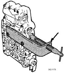
27.
Install spring compressor tool (J35924). Compress spring (55), then remove valve retention pin (56). Carefully release
spring force by rotating tool handle counterclockwise. Remove spring compressor tool.
28.
Remove stop (57), spring (55), and main regulator valve (58).
29.
Push against stop (59) to compress spring (60) and remove valve retention pin (61). Slowly release pressure against stop
(59) and remove stop, spring, and main control valve (62).
30.
Remove valve retention pin (63), stop (64), spring (65), and C2 latch valve (66).
31.
Remove retention pin (67), stop (68), spring (69), and exhaust back pressure valve (70).
J35924