TM 9-2320-302-34
0041 00-13
PISTON AND CYLINDER ASSEMBLY MAINTENANCE - CONTINUED
0041 00
INSTALLATION - CONTINUED
9.
Perform procedures in step 1 through 8 for remaining cylinder liners (3) being installed.
10.
Perform cylinder block pressure testing (WP 0040 00).
NOTE
•
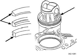
Fire (top) compression ring has plasma (dull finish) face. Top of fire compression ring is identified by
vendor’s mark: dimple or color dot located 30 degrees from ring gap.
•
Middle compression ring has chrome (shiny) face. Top of middle compression ring is identified by dim-
ple or color dot located 30 degrees from ring gap. Inner ring edge has groove.
•
Oil control ring has chrome flashed face and can be installed with either side up.
11.
Insert three piston rings (15 and 16) inside cylinder liner, one at a time, using piston dome (14) (inserted upside down
into liner) to push ring down. Insert piston dome into liner to same depth as ring being positioned. This will ensure rings
are parallel with top of liner and positioned in liner within normal areas of ring travel.
14
15
16