TM 9-2320-302-34
0032 00-18
CYLINDER HEAD REPAIR - CONTINUED
0032 00
ASSEMBLY - CONTINUED
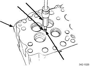
15.
Insert injector tube reconditioning set flaring tool (65) through small hole in bottom of injector tube (64) and rotate flar-
ing tool to engage threads in injector tube reconditioning set installer (28).
16.
Using torque wrench and standard 9/16 in socket, thread flaring tool (65) into injector tube reconditioning set installer
(28) until it flares injector tube (64).
17.
Rotate flaring tool (65) and apply pressure to flare end of injector tube firmly against cylinder head (2). Do not exceed
30 lb-ft (41 Nm).
18.
Remove flaring and installer tools. Ensure proper flare.
NOTE
Turn reamer in clockwise direction only when inserting and withdrawing reamer.
19.
Insert injector tube reconditioning set seat reamer pilot (66) into injector bore until it contacts cylinder head. Insert
reconditioning set seat tip reamer pilot (67) into seat reamer until it bottoms.
20.
Apply a few drops of cutting oil on cutting edges of injector tube reconditioning set tube tip reamer (68) and install in
pilot (67).
21.
Use speed handle with 7/16 in socket to turn tube tip reamer (68) in clockwise direction. Use light pressure until reamer
goes completely through end of injector tube.
WARNING
Compressed air used for cleaning or drying purposes, or for clearing restrictions, should never exceed 30 psi
(207 kPa). Wear protective clothing (goggles/shield, gloves, etc.) and use caution to avoid injury to person-
nel.
22.
Remove reamer and pilot. Use compressed air to clear out injector tube and tip.
2
64
65
28