TM 9-2320-302-34
0029 00-6
OIL PUMP MAINTENANCE - CONTINUED
0029 00
DISASSEMBLY - CONTINUED
NOTE
Two steel locating dowels (one solid diamond-shaped dowel and one tubular-shaped dowel) installed on
pump body mounting legs are pressed in bores to specified depths. Both dowels are extremely durable and
should never need to be replaced.
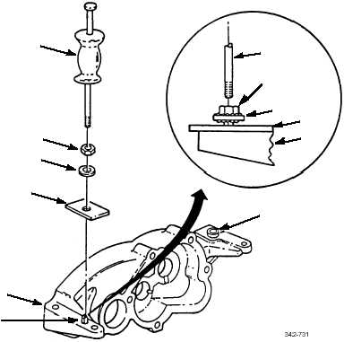
7.
If removal of either dowel (26 or 27) is required, place protective plate (28) on smooth surface of mounting leg (29) over
dowel to be removed. Tack weld washer (30) and nut (31) to dowel.
NOTE
Secure pump body in soft-jawed vise with machined (smooth) surfaces of mounting legs facing up.
8.
Attach slide hammer (32) to welded nut (31) on dowel (26 or 27) being removed, and apply short upward shocking
actions until dowel is freed from bore. Discard dowel with welded nut and washer.
INSPECTION
1.
Inspect all parts for wear or damage.
2.
Discard pump body or pump cover if cracked or if evidence of spun bushings on bushing bores is visible.
3.
Inspect bushings in pump body and cover. Shaft-to-pump body bushing clearance with new parts is 0.0016-0.0024 in
(0.04-0.06 mm). Maximum allowable shaft-to-pump cover bushing clearance with used parts is 0.0035 in (0.089 mm).
32
31
30
28
24
26
32
31
30
28
29
27


