WIRE CHECK PROCEDURES
W T E C I I I E L E C T R O N I C C O N T R O L S T R O U B L E S H O O T I N G M A N U A L
0011 00-31
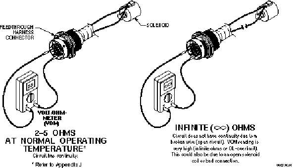
a. At the transmission connector, check the resistance of the A solenoid circuit. Resistance of a
solenoid circuit should be 2.4–5 Ohms — covering a temperature range of –18°C to 149°C
(0°Fto300°F). No continuity in the circuit (infinite resistance) indicates an open in the internal
harness, the feedthrough connector, or the solenoid coil. Locate and repair the open in the internal
harness or replace the internal harness, replace the feedthrough connector, or replace the solenoid.
Figure 4–3. Checking Continuity
b. If the resistance check is good, check the harness for shorts between wires and to ground by per-
forming the following (refer to Figure 4–4):
(1) At the transmission connector, touch one probe of the VOM to one wire of the circuit being
tested and touch the other probe to each terminal in the connector and to chassis ground and
the transmission main housing. Do this for both wires in the circuit being tested.
(2) If the VOM shows zero to low resistance, or the continuity beeper sounds, there is a short
between the two points being probed, wire-to-wire or wire-to-ground. An indication of a short
may be caused by a splice to the wire being checked. Check the wiring diagram in Appendix J
for splice locations. If the short is not a splice, then isolate and repair the short.
CAUTION:
The cleaning solvent must not be chlorine based, contain petroleum distillates, or
conduct electricity. The cleaning solvent should evaporate quickly to prevent the
possibility of condensation within the connectors. Always blow or shake any excess
cleaner from the connector before assembling it to its mating connector or hardware.
Cleaner trapped in the connector can affect the connector seal.