W T E C I I I E L E C T R O N I C C O N T R O L S T R O U B L E S H O O T I N G M A N U A L
WIRE CHECK PROCEDURES
0011 00-30
(2) On the opposite end of the harness, check the continuity of the jumpered pair. No continuity in a
jumpered pair circuit (infinite resistance reading) indicates an open in the wire being tested.
Locate and repair the damaged portion of the wire.
b. If the continuity check is good (0–2 Ohms resistance), remove the jumpers. Check the harness for
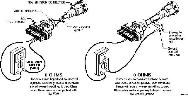
shorts between wires and shorts-to-ground by performing the following (refer to Figure 4–2):
(1) At the ECU end of the harness, touch one VOM probe to one wire of the circuit being tested
and touch the other probe to each terminal in the same connector, then touch the probe to chas-
sis ground and to the transmission main housing. Do this for both wires in the circuit being
tested.
(2) If at any time the VOM shows zero to low resistance, or the meter’s continuity beeper sounds,
there is a short between the two points being probed — wire-to-wire or wire-to-ground. Isolate
and repair the short.
Figure 4–2. Short Between Wires and to Ground
4–2.
CHECKING AT TRANSMISSION CONNECTOR AND THE INTERNAL HARNESS
FOR OPENS, SHORTS BETWEEN WIRES, AND SHORTS-TO-GROUND
1.
Disconnect the external wiring harness from the transmission.
2.
Inspect the connectors. Any terminals which are corroded or dirty must be thoroughly cleaned.
3.
If the connectors are clean and connected correctly, determine which wires in the harness to test. Use
the diagnostic code system schematic to locate the wire terminals. For this example, Code 41 12 indi-
cates an open or short-to-ground in solenoid “A” circuit — wires 102-T1 and 120-T4 (refer to Figure
4–3 and 4–4).


