TM 9-2320-283-20-3
6. Template (5).
Remove.
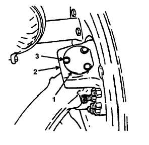
7. King pin cover plate (1) and
Install and secure onto steering
and three bolts (3).
knuckle housing (2).
NOTE
STEERING SYSTEM
3-217.1. STEERING STOP INSPECTION AND ADJUSTMENT PROCEDURES (Continued).
LOCATION/ITEM
ACTION
REMARKS
INSPECTION/ADJUSTMENT (Continued).
NOTE
Brake drum must be turned full right before performing
step 6.
Perform same procedure
(steps 1 thru 5) for the
right side steering stop ad-
justment.
Follow-on maintenance action required:
Paint new steering arm (TB 43-0209).
Grease the steering knuckles and drag link (LO
9-2320-283-12).
Install both front wheels and torque lug nuts (TM 9
2320-283-20).
Change 1 3-1304.5

