TM 9-2320-283-20-3
STEERING SYSTEM.
3-217.1. STEERING STOP INSPECTION AND ADJUSTMENT PROCEDURES (Continued).
LOCATION/ITEM
ACTION
REMARKS
INSPECTION/ADJUSTMENT (Continued).
NOTE
l A 3/16-inch spacer must be used when adjusting the
steering stops in order to acquire the correct steer angle.
l Inspect stop bolts, replace if bent or damaged.
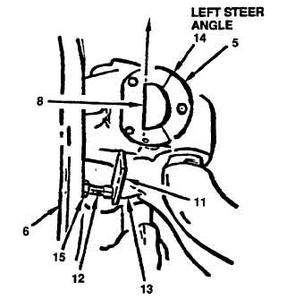
5. 3/16-inch spacer (11), steer-
Position, adjust and tighten.
ing stop bolt (12), steering
Position the spacer be-
tween the steering stop
stop boss (13), wheel hub
bolt and steering stop
(6), king pin line (8) 32 de-
boss. Turn wheel hub full
gree reference line (14) and
left until king pin line
jam nut (15).
aligns with the 32 degree
reference line on template.
If the 32 degree reference
line does not line up with
the king pin line, adjust
steering stop bolt inwards
or outwards, as required,
until the two lines align.
Tighten jam nut and re-
move spacer.
LEFT STEER ANGLE SHOWN
RIGHT STEER ANGLE OPPOSITE
3-1304.4
Change 1

