TM 9-2320-273-20
2-51. BLACKOUT LIGHTING SYSTEM (Continued).
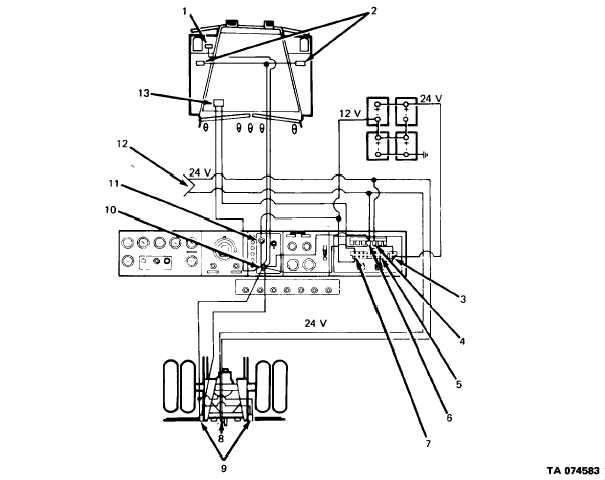
9. REAR BLACKOUT LAMPS. Contains the bulbs for blackout tail and stop lamps. The black-
out tail lamp is energized when the operation switch is in BLACKOUT and the headlamp
switch is in either ON position. The stop lamps are energized when the stop lamp switch is
actuated.
10. OPERATION LAMP SWITCH. Two-position switch for NORMAL and BLACKOUT modes
of operation. With this switch in the BLACKOUT position, 12-volt battery power is avail-
able from the headlamp switch to energize: blackout headlamp, marker lamps, tail lamps,
and relay K4 and K5.
11. HEADLAMP SWITCH, Three-position switch with one OFF position and two ON positions.
The switch supplies 12-volt battery power to the OPERATION lamp switch.
12. 24-VOLT TRAILER RECEPTACLE (M915, M916, and M920). Tractor mounted 12-pin
connector to provide 24-volt battery power to trailer blackout tail and stop lamps.
13. STOP LAMP SWITCH. The stop lamp switch is part of the brake system and is shown and
described in paragraph 2-63. In this circuit, the switch receives 12-volt battery power from
circuit breaker CB-1. When the brakes are engaged, the switch closes and supplies 12-volt
power through the operation lamp switch to energize relay K4. With this relay closed, 24-
volt battery power is supplied through circuit breaker CB-8 to the 24-volt tractor mounted
trailer receptacles.
2-59


