TM 9-2320-273-20
Section XX ELECTRIC HORN
2-53. INTRODUCTION.
The electric horn circuit is identical on all M915 thru M920 vehicles.
2-54. ELECTRIC HORN
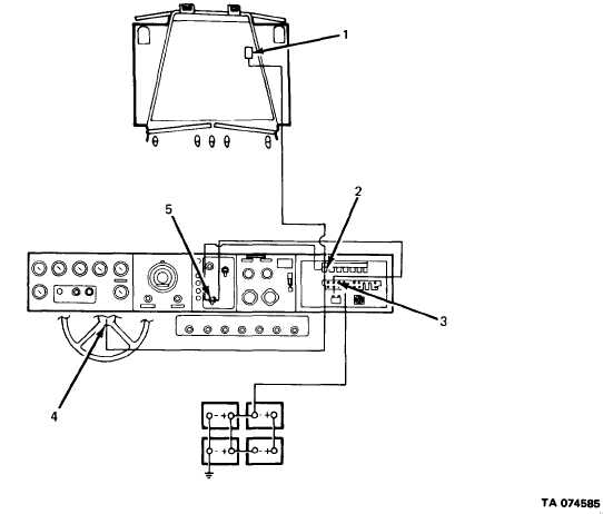
1. ELECTRIC HORN. The horn is energized by 12-volt battery power when horn button is
depressed and operation lamp switch is in NORMAL position.
2. RELAY (K1). When horn button is depressed, coil of relay is energized by 12-volt battery
power from circuit breaker. With relay de-energized, 12 volts are supplied from a second lead
from circuit breaker, through operation lamp switch, through contacts of relay to horn.
3. ClRCUIT BREAKER (CB-2) Protects electrical components of horn circuit by opening when
load exceeds 20 amps. Automatically recycles until overload is removed.
4. HORN BUTTON. Pushing this button activates the horn circuit and energizes the horn.
5. OPERATION LAMP SWITCH. Two-position switch for normal and blackout modes of opera-
tion. With switch set to NORMAL and horn button depressed, 12-volt battery power from
circuit breaker passes through switch contacts to relay.
2-61


