TM 5-2330-325-14&P
4-52A. ABS WHEEL SENSOR (Continued).
b.
Installation.
(1)
Apply a mineral oil-based grease (ref. item 10, Appendix F) that contains molydisulfide to
the sensor spring clip and to the body of the sensor. The grease must be anti-corrosive
and contain adhesive properties that will continuously endure temperatures from -40 to
302 F. (-40 to 150 C).
(2)
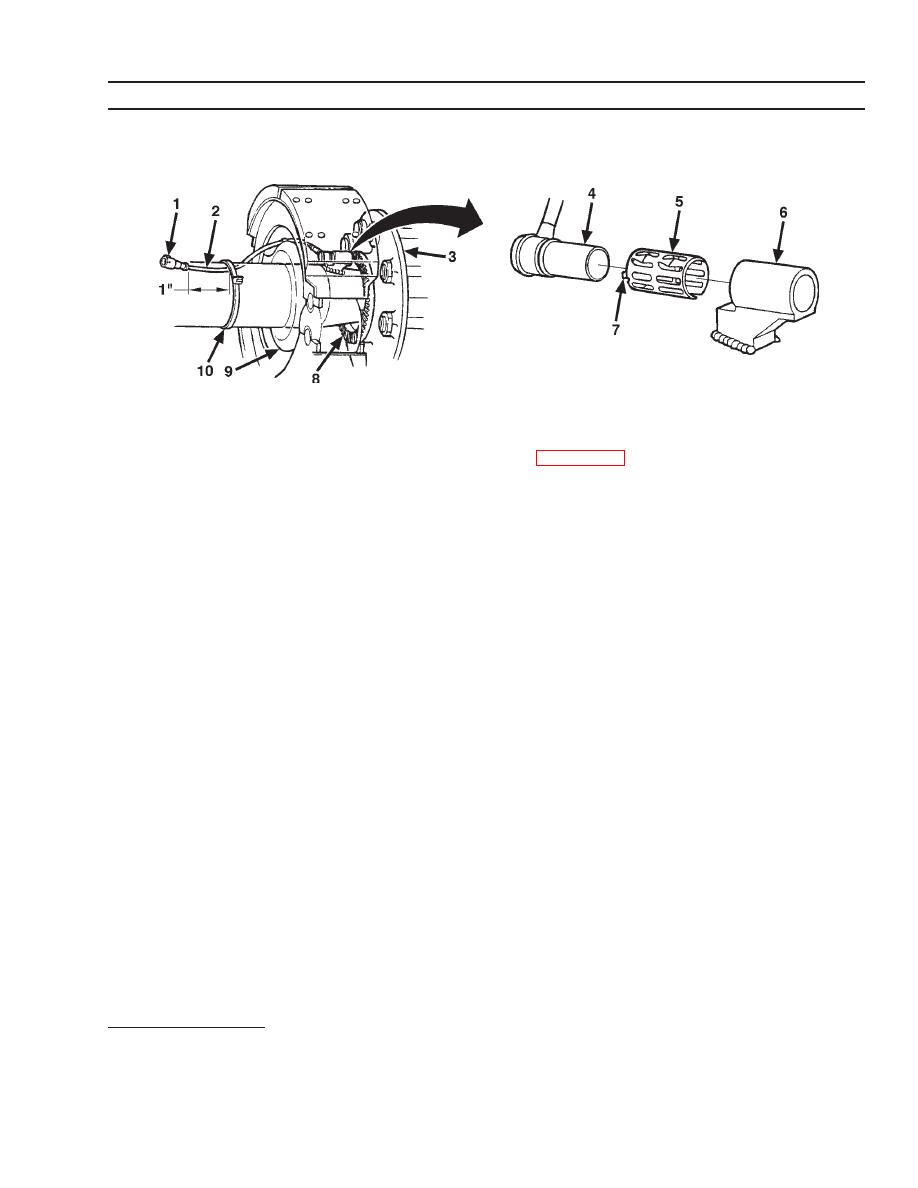
Push the spring clip (5) into the sensor holder (6) from the inboard side until the spring clip
tabs (7) are against the sensor holder (6).
(3)
Push the sensor (4) into the spring clip (5) as far as possible.
(3)
Route the sensor cable (2) toward the brake chamber, over the brake spider (9), and
behind the axle. Use a zip ties (10) to secure the cable to the axle between the brake
spider and the suspension brackets. Locate the zip ties one inch from the molded sensor
plug (1). Continue to route the sensor cable behind the spring seats.
(4)
Install the wheel hub (3) carefully, so that the tooth wheel (8) pushes against the sensor
as you adjust the wheel bearings. After installation there should be no gap between the
sensor (4) and the tooth wheel (8). During normal operation a gap of 0.040 in. is
allowable.
c.
Sensor Output Voltage Test.
(1)
Use a volt/ohm meter to check the AC output voltage of the sensors while rotating the
wheel at approximately one-half revolution per second. Minimum output must be greater
than 0.2 volts AC. If minimum output is less than 0.2 volts AC, push the sensor (4) toward
the tooth wheel (8). Recheck the sensor output.
FOLLOW-ON TASKS:
None.
4-69


