
TB 9-2320-360-13&P-1
A/C KIT INSTALLATION - CONTINUED
0003 00
IN-CAB COMPONENTS - CONTINUED
0003 00
N OT E
If required, remove dash panel/C4ISR mount panel to gain access to wire 1280.
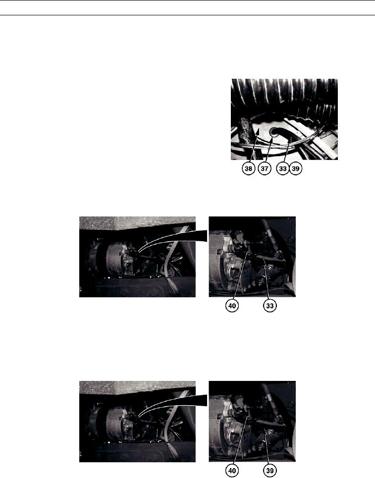
(2)
Route original wire 1280 (33) back
through grommet (37) in bottom of elec-
tronic control box assembly (38).
(3)
Route new wire 1280 (39), provided
with the kit, through grommet (37) in
bottom of electronic control box assem-
bly (38).
(4)
Route new wire 1280 (39) to positive (+)
terminal of alternator (40), along same
path used by original wire 1280 (33).
HETF00327
(5)
Remove original wire 1280 (33) from alternator positive (+) terminal of alternator (40).
HETF00328
CAU T I ON
Ensure new wire 1280 to alternator is loose enough to allow for alternator belt adjustment. Failure to follow
this caution may result in damage to equipment.
(6)
Connect new wire 1280 (39) to alternator positive (+) terminal (40).
HETF00329
0003 00-30