
TB 9-2320-335-13&P
Section II. ILLUSTRATED MANUFACTURING INSTRUCTIONS (Cont'd)
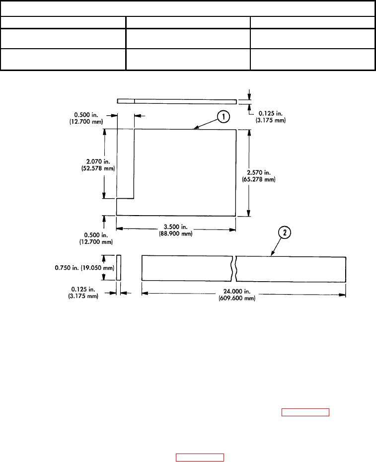
MATERIAL BLOCK
STOCK SIZE
DESCRIPTION
SPECIFICATION
0.125 X 2.570 X 3.500 in.
ALUMINUM FLAT SHEET
IAW ASTM B 209
(3.175 X 65.278 X 88.900 mm)
0.125 X 0.750 X 24.000 in.
ALUMINUM RECTANGLE
IAW ASTM B 211
(3.175 X 19.050 X 609.600 mm)
Figure D-107. Pulley Alignment Tool Fabrication.
INSTRUCTIONS:
NOTE
Remove all burrs and sharp edges from aluminum sheet
and rectangle.
Pulley alignment tool can be assembled using nuts, bolts,
rivets, or by welding.
1. Cut aluminum sheet (1) to size as shown.
2. Position aluminum rectangle (2) on top of aluminum sheet (1) as shown in figure D-107.
NOTE
Check all measurements before welding, riveting, or bolting
pulley alignment tool together.
3.
Assemble pulley alignment tool as shown in figure D-107.
D-3