
DRAIN HOSE INSTALLATION
1. Locate drain hose kit provided in A/C kit.
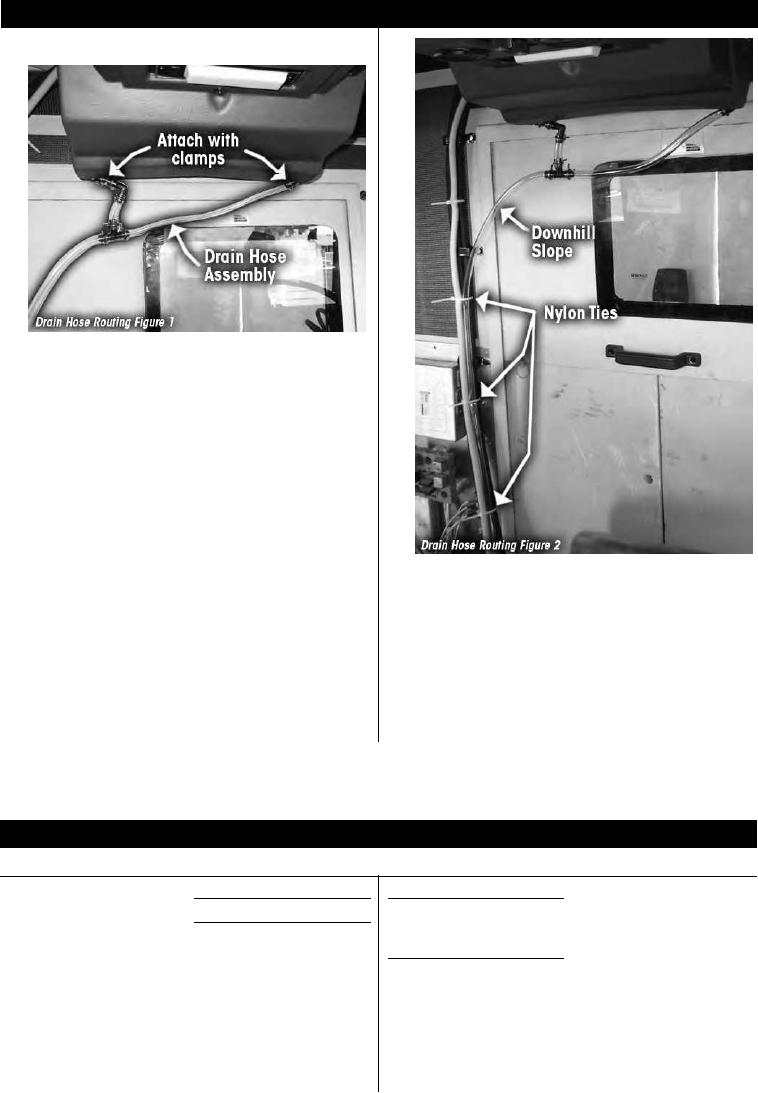
2. Attach drain hose assembly to evaporator unit drain tubes
with clamps provided. See figure 1
3. Route drain hose over to A/C hoses then down through
cone grommet between A/C bulkhead fittings.
4. Be sure hose is routed continuously downward with no
up-hill sections. Secure to refrigerant hoses with nylon ties.
Do not over-tighten nylon ties and collapse drain hose.
See figure 2
5. Underneath cab, cut Drain hose to (if necessary) length
so that approximately 5 inches protrude through grommet.
Retrieve plastic coupler from trimmed end of hose.
Reinstall plastic coupler to end of hose and attach rubber
duck bill (from drain hose kit) to coupler. Duck bill prevents
dust and insects from being sucked into evaporator drain.
CHARGING REFRIGERANT SYSTEM
Charging must be done by a certified A/C technician. Charge ports are near the compressor.
Refrigerant
Compressor oil
R-134a
PAG SP15
Refrigerant charge 3.25 Lbs
Oil charge
270 CC
(supplied in compressor)
(new system)
RD-2-4663-0 (REV --)
M915A2
PAGE 15