
15. Secure chassis harness and diode assembly with nylon ties.
NOTE: Steps 16 through 21 must be performed AFTER
armor has been installed.
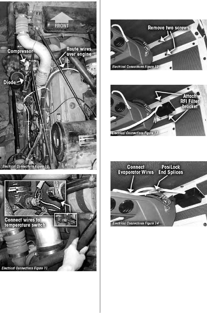
16. Remove and save two screws on top and rear armor plates
near evaporator fittings. See figure 12
17. Locate RD-2-4618-0 RFI filter assembly Attach RFI filter
bracket using locktite and original screws as shown in
figure 13.Tighten screws to 15 lbs/ft per armor installation
instructions.
18. Cut existing terminals off evaporator harness and strip ends
of wires. Connect wires from evaporator unit to matching
wires on RFI filter using PosiLock end splices. See figure 14
14. Route remaining chassis harness wires over engine to
engine coolant temperature switch. Connect wires to
switch in parallel with existing wires as shown in figure 10
& 11.
RD-2-4663-0 (REV --)
PAGE 13
M915A2