TM
9-2320-363-20-1
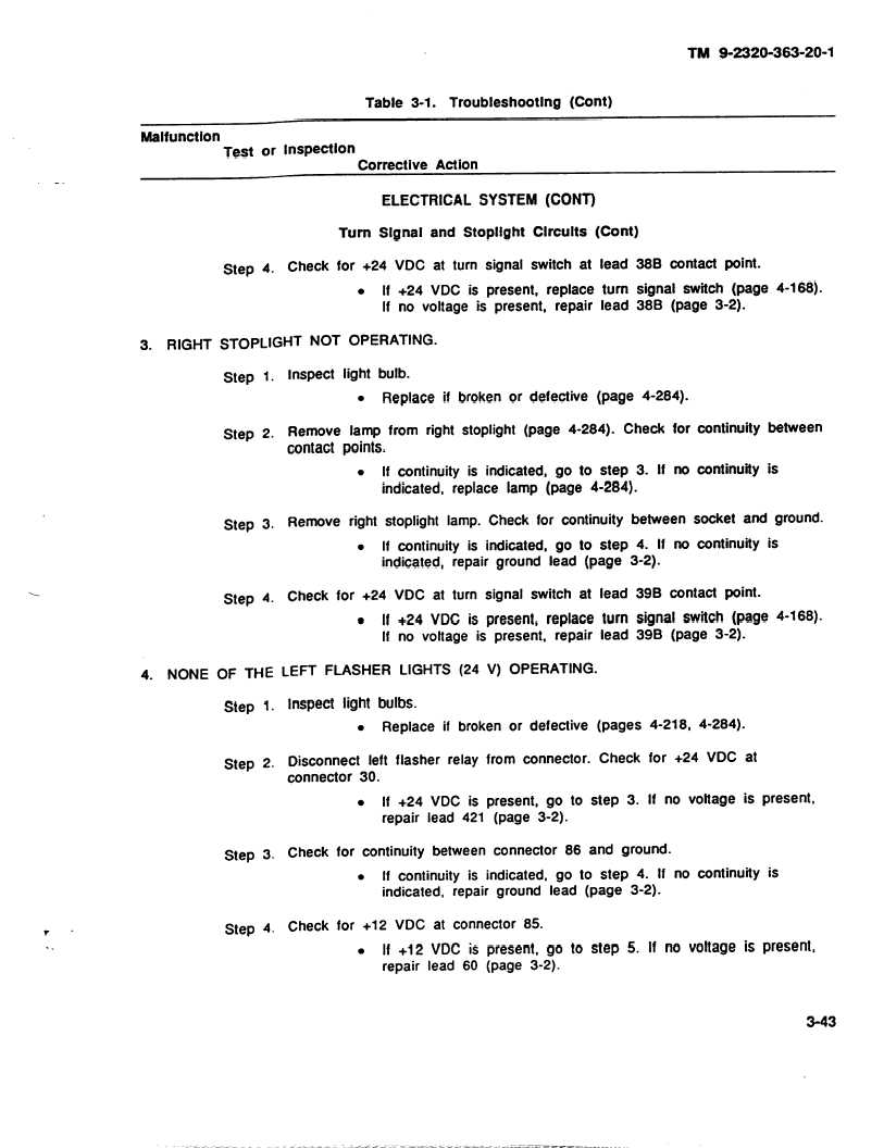
Table 3-1.
Troubleshooting
(Cont)
Malfunction
Test
or Inspection
Corrective Action
ELECTRICAL SYSTEM (CONT)
Turn Signal and Stoplight Circuits (Cont)
Step
4.
Check for +24 VDC
at turn
signal
switch
at
.
If +24
VDC
is present,
replace
If no voltage is present,
repair
lead
turn
lead
38B contact point.
signal switch (page
38B
(page 3-2).
3.
RIGHT STOPLIGHT NOT OPERATING.
Step
1.
Inspect
light bulb.
l
Replace
if broken or defective
(page
4-284).
Step
2.
Remove
lamp from right stoplight (page 4-284).
Check
for
contact points.
.
If continuity is indicated, go to step 3. If no
indicated,
replace lamp (page 4-284).
4-168).
continuity between
continuity is
Step 3.
Remove
right stoplight lamp. Check for continuity between
socket and ground.
.
If continuity is indicated, go to step 4. If no continuity is
indicated,
repair ground lead (page
3-2).
Step
4.
Check for +24 VDC
at
turn
signal
switch
at
lead
39B
contact point.
.
If +24 VDC is present, replace turn signal switch (page
If no voltage is present,
repair lead 39B
(page 3-2).
4.
NONE
OF THE
LEFT
FLASHER
LIGHTS
(24 V) OPERATING.
Step
1.
inspect light bulbs.
.
Replace
if broken or defective
(pages
Step
2.
Disconnect
left
flasher
relay
from
connector.
Check
connector
30.
.
If +24 VDC
is present, go to step 3.
repair lead 421 (page 3-2).
4-168).
4-218,
4-284).
for +24 VDC
at
If no voltage is present,
Step
3.
Check for continuity between connector 86 and ground.
.
If continuity is indicated, go to step 4. If no continuity is
indicated,
repair ground lead (page
3-2).
Step 4.
Check for +12 VDC
at connector 85.
l
If +12 VDC
is
present, go to step 5. If no voltage
is present,
repair lead 60 (page 3-2).
3-43