TM 9-2320-302-34
0082 00-20
REAR-REAR AXLE DIFFERENTIAL CARRIER REPAIR - CONTINUED
0082 00
ASSEMBLY - CONTINUED
44.
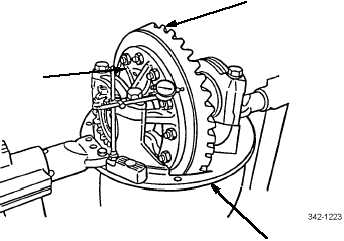
Rotate ring gear (2) while reading dial indicator; runout must not exceed 0.008 in (0.200 mm).
45.
If runout is exceeded, perform disassembly steps 9 through 11.
46.
Inspect all ring gear subassembly (10) parts and differential carrier (1) for possible excessive runout caused. Replace
defective part(s).
47.
Repeat steps 36 through 46.
48.
Attach dial indicator on mounting flange of differential carrier (1) so that plunger is against tooth surface on drive side
of ring gear (2) and zero indicator.
NOTE
Move ring gear only when adjusting backlash.
49.
While holding drive pinion shaft (3) in position, rotate ring gear (2) slightly in both directions against drive pinion shaft.
Note measurement.
NOTE
•
If same ring gear and drive pinion have been installed, adjust backlash to setting recorded in disassem-
bly, step 5.
•
If new ring gear and drive pinion have been installed, adjust backlash to 0.012 in (0.305 mm).
50.
If backlash measurement is less than specified, loosen adjusting ring (9) on back surface of ring gear (2) and equally
tighten adjusting ring (9) on tooth side of ring gear. Repeat step 49.
51.
If backlash measurement is more than specified, loosen adjusting ring (9) on tooth side of ring gear (2) and equally
tighten adjusting ring (9) on back surface of ring gear. Repeat step 49.
52.
Repeat steps 49 through 51 until backlash meets specification. Record setting for use when adjusting pinion bearing pre-
load.
2
1
10


