TM 9-2320-302-34
0041 00-20
PISTON AND CYLINDER ASSEMBLY MAINTENANCE - CONTINUED
0041 00
INSTALLATION - CONTINUED
CAUTION
•
Failure to orient piston connecting rod properly during installation may result in connecting rod striking
and damaging nozzle. A damaged or loosed nozzle can cause a loss of main gallery pressure or lack of
cooling to piston. Severe engine damage would result.
•
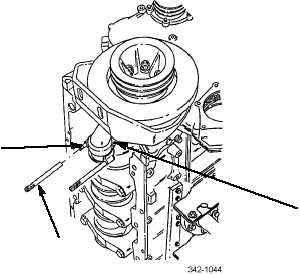
Use care when loading piston into cylinder liner not to damage piston cooling nozzle installed at base of
cylinder bore. Before loading piston into liner, turn connecting rod so that bearing end is offset approxi-
mately 10-15 degrees and is not perpendicular to crankshaft. Once rod end is past nozzle, turn rod so it
is perpendicular with crankshaft.
NOTE
Ensure two connecting rod bolts have not been unseated or turned.
33.
Push or tap connecting rod and piston assembly (9) until upper connecting rod bearing shell is firmly seated on crank-
shaft journal. Remove two connecting rod guides (7).
NOTE
Perform step 34 only if performing plastigauge check. If not performing plastigauge check, go to step 35.
34.
Check clearance between connecting rod bearing shells and crankshaft journal at time of connecting rod and piston
assembly installation as follows:
a.
With upper and lower bearing shells (6) installed in connecting rod and connecting rod cap, wipe any oil from
bearing shells and connecting rod journal.
b.
Place piece of plastigauge (33) along full width of lower connecting rod bearing shell (6) about ¼ in (6.35 mm) off
center.
c.
Install connecting rod and rod bolts on crankshaft bearing journal in its corresponding cylinder.
8
7
9


