TM 9-2320-302-34
0038 00-4
ADJUSTABLE IDLER GEAR REPLACEMENT - CONTINUED
0038 00
INSTALLATION - CONTINUED
8.
Measure gear lash between adjustable idler gear and camshaft drive gear. Using cam/idler lash adjuster, gear lash should
be 0.002-0.009 in (0.051-0.229 mm) for new parts and a maximum of 0.012 in (0.305 mm) for used parts. Reading is
one-half of actual measurement. Multiply reading by 2 to determine specification.
ADJUSTMENT
1.
Loosen three nuts (1) until hand tight.
2.
Insert dowel portion of cam/idler lash adjuster (11) in center hole of retaining plate (2).
3.
Secure engine barring tool (12) to bottom of access cover opening with two access cover bolts (13). Tighten bolts to 20
lb-ft (27 Nm).
4.
Install cam/idler lash pedestal in threaded hole in leg of camshaft drive gear (10).
NOTE
Ensure dial indicator rests squarely on pedestal flat.
5.
Mount dial indicator so stem of indicator rests on scribed line of pedestal flat.
6.
Remove bolt (14) and washer (15).
7.
Turn adjusting screw (16) clockwise to move adjustable idler gear toward camshaft drive gear (10) until there is zero
lash.
8.
Insert screwdriver through access bolt hole (17) and engage adjustable idler gear tooth to determine gear lash.
9.
Apply pressure on screwdriver to hold adjustable idler gear in counterclockwise direction and attempt to move camshaft
drive gear (10) by hand. Watch dial indicator pointer. If there is zero lash, pointer will not move.
NOTE
Gear lash reading obtained on cam/idler lash pedestal is one-half actual gear lash. Reading on dial indicator
must be doubled to determine if specification is met.
10.
When zero lash is obtained, turn adjusting screw (16) approximately 1-1/2 turns counterclockwise or until correct gear
lash is obtained.
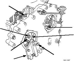
11
1
14, 15
12
10
2
13