TM 9-2320-302-34
0036 00-4
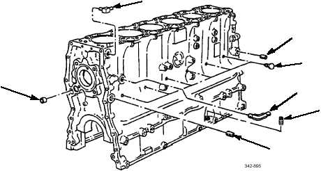
CYLINDER BLOCK ASSEMBLY REPAIR - CONTINUED
0036 00
DISASSEMBLY - CONTINUED
9.
Position cylinder block to view left side.
10.
Remove two pipe plugs (14) and pipe plug (15).
11.
Remove air compressor oil supply line elbow (16).
12.
If installed, remove air compressor coolant supply elbow (17).
13.
Remove six weep hole plugs (18).
14.
Pierce cup plug (19) with screwdriver or chisel. Remove and discard plug.
CLEANING AND INSPECTION
1.
Use general cleaning methods to clean all parts.
2.
Measure each cylinder bore (20) using inside micrometer.
3.
Measure each cylinder bore for following dimensions at locations A, B, and C on axis 90 degrees apart. Dimensions are
average gage readings at each location (Table 1). Taper and out-of-round should not exceed 0.001 in (0.0253 mm):
Table 1. Cylinder Bore Dimensions.
LOCATION
DIMENSION
A
5.868-5.871 in (149.050-149.120 mm)
B
5.750-5.753 in (146.050-146.120 mm)
C
5.750-5.753 in (146.050-146.120 mm)
14
15
17
18
14
16
19