
TM 5-2330-361-14&P
Install yoke and locknut on push
positioned down.
Draw the clamp lugs together and start the
g.
Install yoke pin on slack adjuster and adjust
rod.
clamp bolts and nuts. Tighten these evenly to 120-
Check the angle formed by the slack ad-
brakes.
1 3 0 inch lbs. (1.38-1.50 kg-m) (Bendix. Westing-
juster and push rod with the brakes applied. This
house).
9 00. Turn the yoke to
angle should not be less than
obtain the desired angle. The angle should be the
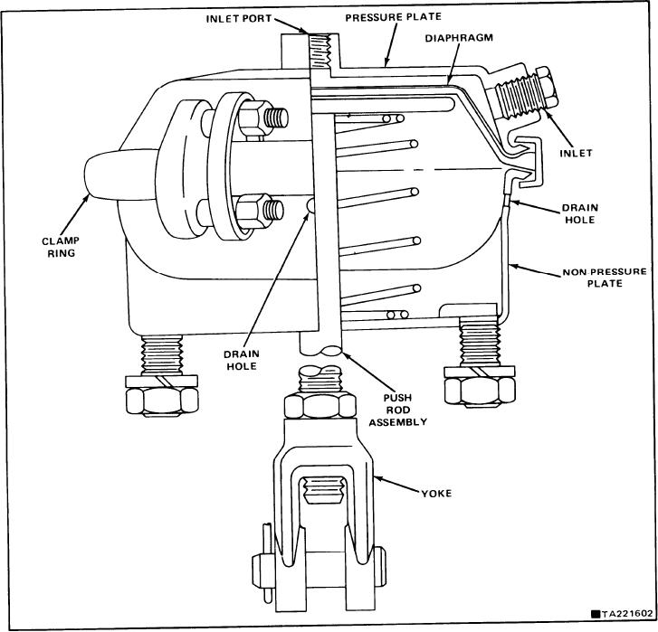
7-19. INSTALLATION.
same for all slack adjusters when the brakes are
7-20. Place brake chamber in mounting bracket and
adjusted.
The drain hole should be
tighten nuts on studs.
FIGURE 7-4. BRAKE CHAMBER.
Change 3
7-4