Mark lines.
10-21.2. STEERING STOP INSPECTION AND ADJUSTMENT PROCEDURES (Continued).
LOCATION/lTEM
ACTION
REMARKS
NOTE
Check that alignment marks on the pitman arm steering gear sector shaft
are in alignment before performing the steering stop adjustment proce-
dure.
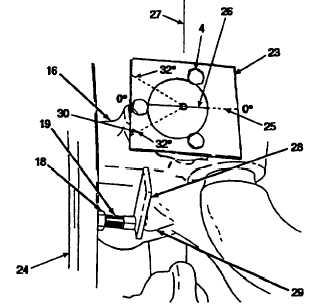
1. Template (23), steering knuckle housing (16),
Install.
Put template on top of
and three cover bolts (4).
housing, and partially in-
stall bolts to position tem-
plate.
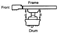
2. Front brake drums (24).
Center and
Make two measurements,
measure.
the first at the forward side
of the brake drum, meas-
uring the distance “d” from
the frame to the back of
the brake drum. Then
make the same measure-
ment at the rear of the
brake drum. Adjust as
necessary to make the
measurements equal.
3. Template (23).
Put straight edge on zero
degree reference line (25)
and mark a line (26)
across the king pin. Line
(26) should be perpendicu-
lar to the line of travel (27).
NOTE
A 1/8-inch spacer must be used when adjusting the steering stops in order
to acquire the correct steer angle.
4. 1/8-inch spacer (28), steering stop bolt (19),
Position, adjust,
Put spacer between
steering stop boss (29), brake drum (24),
and tighten.
steering stop bolt and
king pin line (26), 32 degree reference
steering stop boss, turn
line (30), template (23), and jam nut (18).
brake drum full left
until king pin line aligns
with 32 degree reference
line on template. If the 32
degree reference line
does not line up with the
king pin line, adjust steer-
ing stop bolt. Tighten jam
nut and remove spacer.
Change 3 10-84.9
STEERING MECHANISM.
TM 9-2320-273-20