
10-16. Feather edging, scuffing, and uneven wear
c.
Distance "R" and "L" should be equal, If
of tires show need for alignment check.
"scuff"
n o t , make adjustment of alignment screws using
has to be checked on a wheel alignment tester. A
procedure given in paragraph 10-7 until equal "R"
reading of 16 ft. (4.88 metres) runout per mile or less
and "L'' distance is obtained.
indicates satisfactory alignment.
A reading in ex-
cess of 16 ft. (4.88 metres) per mile reveals a need
10-7. TANDEM ALIGNMENT PROCEDURE.
for checking the cause of excessive runout. Check
the wheel bearings, and check for wheels which are
10-8. If the unit is steering left, as shown in figure
If the wheel bearing and wheel
bent or broken.
10-2, correct the alignment as follows:
c h e c k reveal nothing, c h e c k for bent axles and
spindles.
a , Loosen all locknuts at points "A" and "B"
(see figure 10-3).
10-17.
C H E C K I N G AXLE SPACING - SECOND
ALIGNMENT TEST.
b. Loosen the four (4) alignment screws "A" and
tighten the four (4) alignment screws "B". Continue
this procedure until tandem is in alignment.
1 0 - 1 8 . Another check to determine the causes of
the wear characteristics above is as follows:
NOTE:
To prevent ports from binding, it is recom-
a.
With trailer unloaded, see that all axles are
mended that pairs of screws be tightened
at the same time.
level.
c. Tighten all locknuts after tandem is aligned
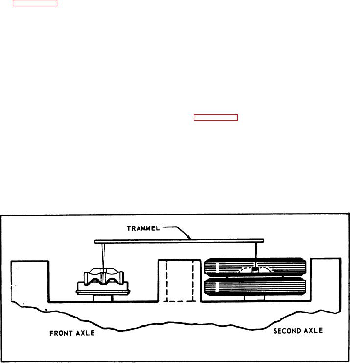
b. Remove hub caps and, using trammel equipped
and screws are tight.
with extended points, check center distances of the
first and second axle on both sides of the trailer
d. If unit is steering right, loosen the four (4)
(see figure 10-5).
alignment screws "B" and tighten the four (4) align-
ment screws "A", the opposite of above procedure.
If above distances vary more than 1/16 in.
c.
1.59 mm), check further
for
bent
spindle,
axle
or
10-14. CORRECTING TIRE SCUFF AND UN-
other mechanical damage.
EVEN WEAR.
10-19. CHECKING AXLE FOR BEND.
10-15. CHECKING TIRE SCUFF - FIRST WHEEL
ALIGNMENT TEST.
1 0 - 2 0 . Scuffed tires or uneven wear may indicate
a bent axle. Check as follows:
FIGURE 10-5. MEASURING AXLE CENTERS.
10-2.

