
7-1. GENERAL.
This fills the brake chambers with
the service line.
the same pressure as the service line, thus applying
7-2.
the brakes.
This section contains a description of the
operation of the trailer brake air supply system.
d. Releasing the service brakes will cause the
Also included in this section ore test instructions
pressure in the service line to decrease, thus caus-
and disassembly and assembly procedures.
sure from the brake chambers.
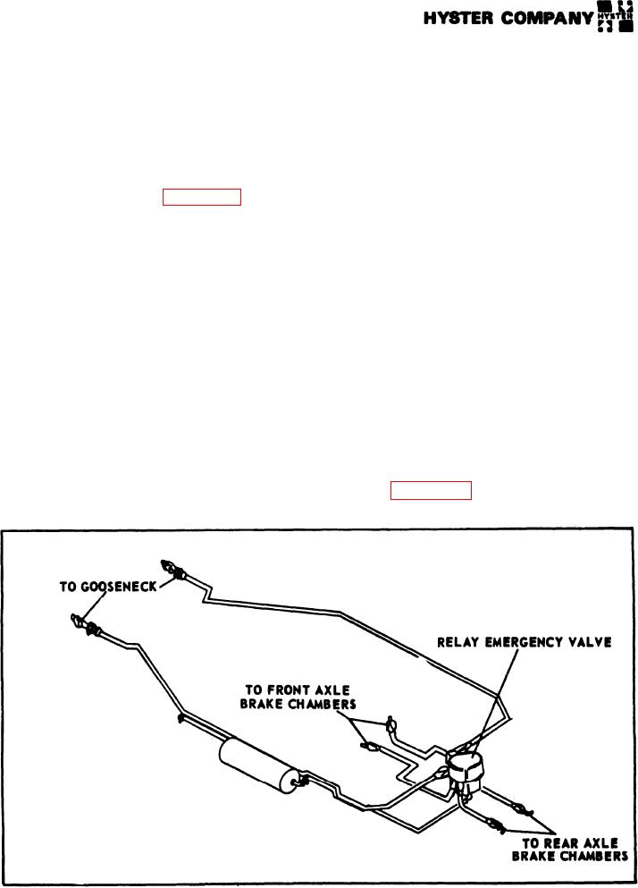
7-3. BRAKE AIR SUPPLY SYSTEM
DESCRIPTION (see figure 7-1).
e. The trailer brakes con also be applied inde-
pendently from the tractor brakes by application of
7-4. The trailer relies on the tractor for its air
a hand controller, which supplies air pressure to the
supply. A description of normal operation follows:
service line.
When the service and emergency lines are
O.
f. Brakes will also be applied by reducing the
c o n n e c t e d to the towing vehicle, the reservoir is
pressure in the emergency line to about 30 PSI (2.11
charged to approximately the same pressure as is
kg/cm). A gradual reduction in the emergency line
present in the tractor reservoirs. The RE-6 relay
pressure will cause a graduated increase in the pres-
emergency valve will keep the trailer brakes opplied
sure to the brake chambers.
until the
emergency line pressure reaches 60 PSI
( 4 . 2 2 k g / c m2 . Brake application will then be re-
g. A sudden release of pressure in the emergency
leased.
line will cause a full release of reservoir pressure
into the brake chambers with a resultant full brake
b. When the vehicle is traveling over the road,
application.
the brakes are released and the emergency line and
reservoir are charged to full pressure.
7-5. RELAY EMERGENCY VALVE RE-6
(see figure 7-2).
c. When the service brakes are applied normally
in the towing vehicle, the pressure is increased in
7-6. The relay emergency valve senses the line
FIGURE 7-1. BRAKE AIR SUPPLY.
HYSTE COMPANY
1978
7-1.

