
TB 9-2320-360-13&P-1
A/C KIT INSTALLATION - CONTINUED
0003 00
IN-CAB COMPONENTS - CONTINUED
0003 00
8.
A/C Switch Harness Installation.
CAU T I ON
Use caution when drilling and check for components behind panel. Failure to follow this caution may cause
damage to vehicle.
N OT E
Refer to WP 0057 00, Electronic Control Box Template and A/C Electrical and Diagram Schematic.
When drilling in doghouse, drill from bottom up and centered in hole in insulation.
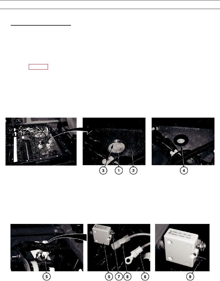
Fan switch (black 5 terminal) connector goes first.
a.
Drill 1/16-inch diameter pilot hole in location shown on template.
b.
Drill a 1 1/2-inch diameter hole (1) through doghouse casing (2) and insulation (3).
c.
Install grommet (4), provided with the kit, in doghouse casing (2).
449-117
d.
Connect harness to A/C circuit breaker.
(1)
Run wiring harness through grommet (4).
(2)
Run wiring harness under air lines to 20 amp circuit breaker (5).
(3)
Connect red power lead (6) to screw terminal (7) on 20 amp circuit breaker (5).
(4)
Connect red power lead (8) to slip-on terminal (9) on 20 amp circuit breaker (5).
HETF00321
0003 00-26

