
TB 9-2320-360-13&P-1
A/C KIT INSTALLATION - CONTINUED
0003 00
UNDER-HOOD COMPONENTS - CONTINUED
3.
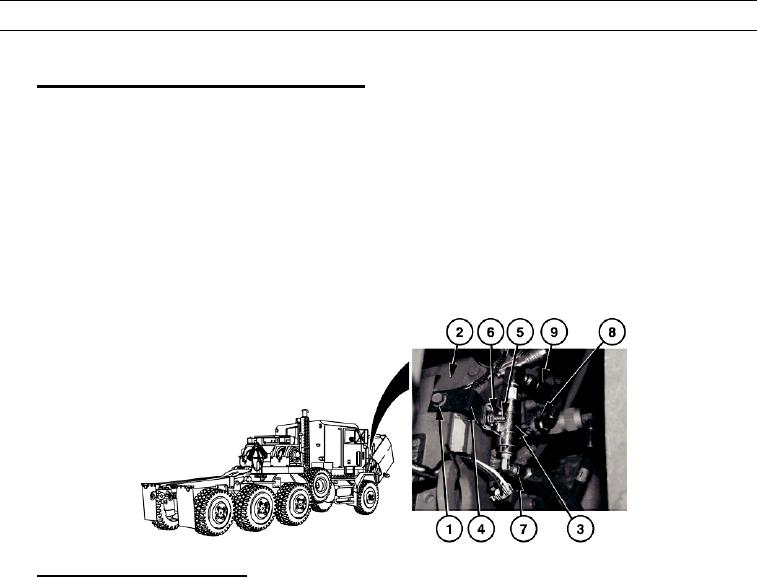
Fan Control Solenoid Switch Assembly Installation.
a.
Remove screw (1) from electronic control module (ECM) (2).
b.
Install A/C fan control solenoid switch assembly (3) on A/C fan control solenoid switch assembly mounting
bracket (4) with screw (5) and locknut (6).
c.
Install A/C fan control solenoid switch assembly mounting bracket (4) on ECM (2) with screw (1).
d.
Remove supply air line (7) from thermostatic switch inlet elbow (8).
e.
Install supply air line (7) on A/C fan control solenoid switch assembly (3).
f.
Install air line (9), provided with the kit, on thermostatic switch inlet elbow (8).
g.
Install air line (9) on A/C fan control solenoid switch assembly (3).
449-600
4.
Water Connections Modification.
CAU T I ON
Ensure hoses are routed so hoses do not kink or rest on hot surfaces after installation. Failure to follow this
caution may result in damage to hoses.
N OT E
Make sure all coolant is drained from system.
a.
Disconnect lower radiator hose (7) from engine water pump (2).
b.
Remove hose and elbow (1) from engine water pump (2). Remove and retain clamp. Discard hose and elbow.
WAR N I N G
Adhesives and sealing compounds can burn easily, can give off harmful vapors and are harmful to skin and
clothing. To avoid injury or death, keep away from open fire and use in well-ventilated areas. If adhesive or
sealing compound gets on skin or clothing, wash immediately with soap and water.
c.
Apply thread tape on threads of straight hose adapter (3), provided with the kit.
d.
Install straight hose adapter (3) on engine water pump (2).
e.
Remove hose and straight hose adapter (4) from engine block (5). Remove and retain adapter and clamp. Discard
hose.
0003 00-6

