
TB 9-2320-335-13&P
12-45. HYDRO-BOOST VENT LINE REPLACEMENT
This task covers:
a. Removal
b. Installation
INITIAL SETUP:
Applicable Models
Manual References
All except M1114
TM 9-2320-387-24P
Tools
Equipment Condition
General mechanic's tool kit:
Engine left splash shield removed
automotive (Appendix B, Item 1)
(para. 10-23 or para. 10-23.1).
Materials/Parts
Maintenance Level
Locknut (Appendix A, Item 77)
Unit
Nut and lockwasher assembly
(Appendix A, Item 197)
a. Removal
1.
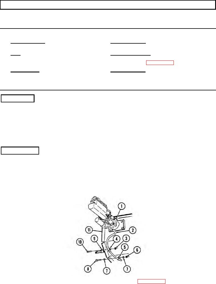
Disconnect hydro-boost vent line (2) from hydro-boost (1).
2.
Remove nut and lockwasher assembly (3), capscrew (10), clamp (4), harness clamp (9), and vent
line (2) from body (11). Discard nut and lockwasher assembly (3).
3.
Remove locknut (6), washer (7), capscrew (8), washer (7), clamp (5), and vent line (2) from body (11).
Discard locknut (6).
4.
Remove two clamps (4) and (5) from vent line (2).
b. Installation
1.
Install two clamps (4) and (5) on vent line (2).
2.
Install vent line (2) and clamp (5) on body (11) with washer (7), capscrew (8), washer (7), and
locknut (6). Tighten capscrew (8) to 6 lb-ft (8 Nm).
3.
Install vent line (2), harness clamp (9), and clamp (4) on body (11) with capscrew (10) and nut and
lockwasher assembly (3).
4.
Connect vent line (2) to hydro-boost (1).
FOLLOW-ON TASK: Install engine left splash shield (para. 10-23 or para. 10-23.1).
12-2

