TM 9-2320-363-20-1
Table 3-1. Troubleshooting (Cont)
Malfunction
Test or inspection
Corrective action
ELECTRICAL SYSTEM (CONT)
Instrument Wiring Circuits (Cont)
7. VOLTMETER DOES NOT OPERATE, WARNING LIGHT OPERATING NORMALLY.
Step 1.
Disconnect lead 19A from voltmeter. Check for +12 VDC at lead 19A.
If +12 VDC is present, go to step 2. If no voltage is present,
repair lead 19A (page 3-2).
Step 2.
Disconnect ground lead from voltmeter. Check for continuity between ground
lead and ground.
If continuity is indicated, replace voltmeter (page 4-172). If no
continuity is indicated, repair ground lead (page 3-2).
8. TACHOGRAPH DOES NOT OPERATE, VOLTMETER AND PANEL LIGHT OPERATING NORMALLY
(M915A2 AND M916A1).
Step 1.
Disconnect lead 172 from tachograph. Check for +12 VDC at lead 172.
If +12 VDC is present, go to step 2. If no voltage is present,
repair lead 172 (page 3-2).
Step 2.
Disconnect ground lead from tachograph. Check for continuity between
ground lead and ground.
If continuity is indicated, replace tachograph (pages 4-178,
4-182). If no continuity is indicated, repair ground lead
(page 3-2).
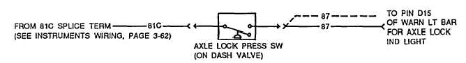
Axle Lock Circuit (M915A2)
1. AXLE LOCK DOES NOT ENGAGE.
Step 1.
Disconnect lead 81C from axle lock pressure switch. Check for +12 VDC at lead 81C.
If +12 VDC is present, go to step 2. If no voltage is present,
repair lead 81C (page 3-2).
3-66 Change 3