
TB 9-2300-420-20-1
PARKING BRAKE CONTROL ASSEMBLY ADJUSTMENT - Continued
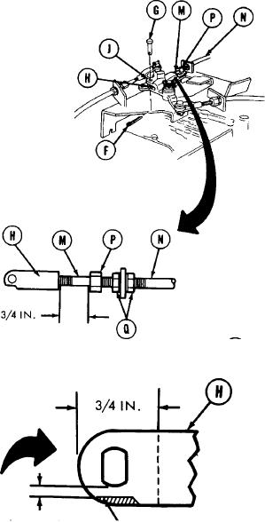
7. Using rule, measure distance between nut (P) and connector (H) after shaft (M) is pushed inward as far as
possible. Record reading.
8. Pull shaft (M) out 3/4 inch farther than reading taken in step 7.
NOTE
Do not change 3/4 inch position when performing steps 9 and 10.
9. Check to see if pin (G) can be freely inserted
through holes in bellcrank (J) and connector (H).
If holes do not line up, loosen two nuts (Q), using
two 15/16 inch open end wrenches. Adjust
control housing (N) until pin can be freely
inserted. Tighten nuts (Q).
10. Install pin (G) and clip (F) in bellcrank (J) and
connector (H).
NOTE
An interference may exist between
the connector (H) and the locating
pin.
If this occurs, it will be
necessary to grind the connector as
shown to eliminate this interference.
3/32 TO 1/16 IN. GRIND OFF
TA173250
12