TM 9-2320-302-20
0228 00-12
GENERAL MAINTENANCE INSTRUCTIONS - CONTINUED
0228 00
MULTIMETER - CONTINUED
CAUTION
Before performing a continuity test, always turn master battery switch to OFF position and disconnect cir-
cuit to be tested. Failure to follow this caution may damage multimeter.
d.
Testing for Resistance. Allowable resistance readings depend on circuit being tested. Refer to the particular sec-
tion dealing with that circuit or component for allowable readings.
(1)
Zero multimeter.
(2)
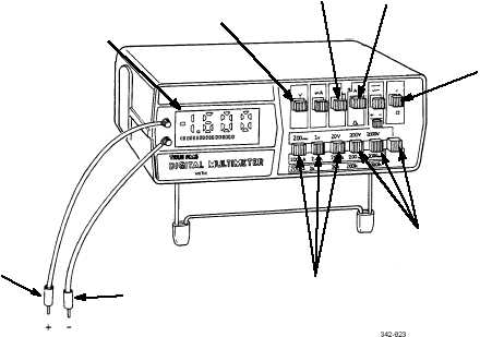
Press OHMS FUNCTION switch (2).
(3)
Press LOWEST VOLTAGE/OHMS selector switch (3). If test calls for ohms range other than RX1, set
RANGE SELECTOR switch (7) to required range.
(4)
Connect black and red probes (4 and 5) across circuit to be tested.
(5)
Read digital readout (6) and interpret results as circuit resistance.
3.
Measuring DC Voltage.
a.
Set multimeter ON/OFF switch (1) to ON position.
b.
Press VOLTS FUNCTION switch (8).
c.
Set AC/DC selector switch (9) to DC.
d.
Select and press LOWEST VOLTAGE/OHMS selector switch (3) for voltage range higher than volts to be mea-
sured.
e.
Connect red probe (5) to positive (+) side of circuit and black probe (4) to negative (-) side of circuit.
f.
Read digital readout (6) and interpret results as DC voltage in circuit being tested.
4
5
6
8
2
9
1
7
3