
TM 5-2330-361-14&P
8. Check installation of slack adjuster by removing clevis pin and lightly push adjuster into clevis and
release. If holes remain in alignment-a proper installation was made. If holes in adjuster and clevis DO NOT
remain in alignment --
a. Realign adjuster with clevis and reinstall clevis pin and retainer.
b. Loosen anchor bracket mounting fasteners.
c. Repeat step 7 and recheck.
9. Prior to release of vehicle for service, initial brake adjustment maybe accomplished by
a. Manually adjusting brakes according to regular practice and procedure.
NOTE
Readjustment of adjuster takes considerable effort and will be accompanied by a ratcheting sound.
-OR-
b. With full pressure in the vehicle air system, operate the service brakes (allow full return on brake
release) until the brake chamber pushrod travel is reduced to within acceptable limits.
Final operating pushrod travels will not be obtained until the vehicle has been driven and the brakes heated.
4 - 30 R e m o v a l
lMPORTANTBefore removing adjusters, CHOCK WHEELS, buildup full system air pressure and place
all brake controls in off or release position. Make certain spring chambers are caged and/or fully released.
1. Remove clevis pin from brake chamber clevis.
2. Using 12mm wrench or socket, turn adjusting hex counterclockwise until adjuster rotates clear of brake
chamber clevis.
NOTE
Rotation of adjusting hex in this direction takes considerable effort, and will be accompanied by a
ratcheting sound. -
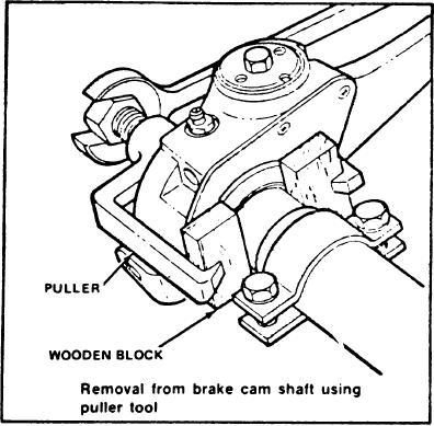
Figure 4 Removal from brake Cam Shaft using puller tool
3. Disconnect control arm lever from anchor bracket by: Remove nut and washers from control arm stud
and bend strap bracket clear of stud.
4. Remove camshaft retaining ring or bolt and spacing washers.
5. Remove adjuster from camshaft. If adjuster does not slide off easily, use a puller tool. DO NOT
HAMMER ON COVER PLATE.
CAUTION
Do not apply puller jaws directly on face of cover-use wooden blocks to prevent internal damage.
Change 2
9

