
TB 9-2320-360-13&P-1
A/C KIT INSTALLATION - CONTINUED
0003 00
FINAL COMPONENT ASSEMBLY - CONTINUED
0003 00
2.
Evaporator Installation.
N OT E
Keep all disconnected A/C hoses, and ports on shutoff valves, compressor, condenser, and receiver/dryer clean
and capped during installation.
The plastic elbows must be oriented with open end toward floor. A 3-inch piece of hose attaches elbow to evap-
orator drain fittings.
A/C evaporator assembly will be shipped with A/C hoses attached and expansion valve installed.
Cork tape is used on expansion valve only.
The alternator access panel is removed to help route A/C lines through grommet on doghouse front engine
access panel.
a.
Remove alternator access panel from doghouse (TM 9-2320-360-20).
b.
Place evaporator assembly on cab floor prior to position for installation.
c.
If necessary, loosen three screws in rear of doghouse to allow access for evaporator to slide in.
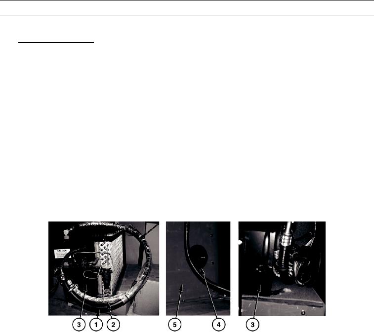
d.
Install two A/C hoses (1 and 2) attached to evaporator assembly (3), through 3-inch grommet (4) on doghouse
front engine access panel (5).
HETF00369
0003 00-34

