
TB 9-2320-335-13&P
6-2. FRONT PROPELLER SHAFT ASSEMBLY MAINTENANCE
This task covers:
a. Removal
c. Installation
b. Inspection
INITIAL SETUP:
Tools
Manual References
General mechanic's tool kit:
TM 9-2320-387-10
automotive (Appendix B, Item 1)
TM 9-2320-387-24P
Maintenance and repair shop equipment:
Maintenance Level
automotive (Appendix B, Item 2)
Unit
Materials/Parts
Cotter pin (Appendix A, Item 21)
Two locknuts (Appendix A, Item 128)
Four lockwashers (Appendix A, Item 145)
(Serial numbers 300000 and above)
NOTE
Propeller shaft bearing caps should be taped together to prevent
loss of bearings.
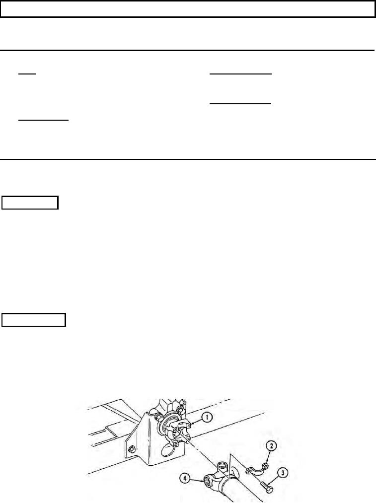
a. Removal
1.
Remove four capscrews (3) and two bearing straps (2) from front propeller shaft assembly (4) and
differential pinion yoke (1).
2.
Remove four nuts (7), lockwashers (8), and two U-bolts (11) from front propeller shaft assembly (4)
and transfer case output yoke (9). Discard lockwashers (8).
3.
Remove cotter pin (14), washer (13), and transfer case shift rod (12) from transfer case shift lever (6).
Discard cotter pin (14).
4.
Remove two locknuts (15), washers (16), capscrews (18), washers (16), and center bearing (17) from
engine mount (19). Discard locknuts (15).
5.
Move front propeller shaft assembly (4) forward, then rearward, over top of transfer case (5) and
b. Inspection
1.
Inspect driveshaft (21) and coupling shaft (22) for cracks and damage. Replace either if cracked or
damaged (para. 6-3).
2.
Inspect grease fittings (23) and universal joints (20) for serviceability. Replace universal joints (20)
or grease fittings (23) if unserviceable (para. 6-3).
3.
Inspect center bearing (17) for roughness or damage. Replace coupling shaft (22) if center bearing (17)
is rough or damaged (para. 6-3).
6-2

