
TB 9-2320-335-13&P
4-18.1. SPEEDOMETER HARNESS ASSEMBLY REPLACEMENT
This task covers:
a. Removal
b. Installation
INITIAL SETUP:
Tools
Equipment Condition
General mechanic's tool kit:
Hood raised and secured (TM 9-2320-387-10).
automotive (Appendix B, Item 1)
Instrument cluster (electronic) removed
Materials/Parts
Sender generator (electronic) removed
Two tiedown straps (Appendix A, Item 324)
Two locknuts (Appendix A, Item 73.1)
Engine access cover removed
(TM 9-2320-387-24-2).
Manual References
TM 9-2320-387-10
Maintenance Level
TM 9-2320-387-24-2
Unit
TM 9-2320-335-13&P, Appendix E
NOTE
Prior to removal, tag leads for installation.
Jumper wires on rear of instrument cluster can be replaced
separately.
Rotate speedometer harness under body harness to keep body
harness from laying on transmission.
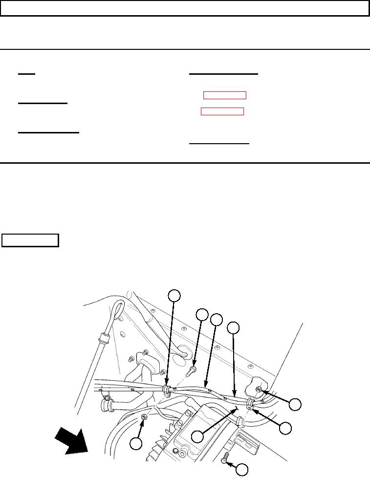
a. Removal
1.
Remove locknut (5), capscrew (7), harnesses (3) and (4), and clamp (6) from cowl (8).
Discard locknut (5).
2.
Remove locknut (9), capscrew (2), clamp (1), and harnesses (3) and (4) from cowl (8).
Discard locknut (9).
1
2
3
4
FR
5
ON
VE OF T
HI
6
CL
E
8
9
7
4-6

