
try the other switch. Red connector to gray switch. Gray
connector to black switch. See figure 7.
9. Route single yellow wire under cab toward passenger
side, along A/C hoses. Route yellow wire up through cone
grommet between bulkhead fittings.
10. Secure yellow wire to hoses with nylon ties.
11. Route remaining chassis harness wires forward along A/C
hoses to compressor.
6. Route power harness across transmission tunnel then
route rearward through wiring tunnel to A/C hose bulkhead
fittings. See figure 5.
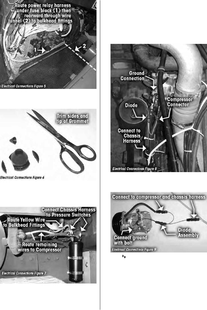
12. Locate RD-6-5307-0 diode assembly in electrical kit.
Connect diode assembly to compressor wire and mating
7. Locate rubber cone grommet in electrical kit. Cut flange of
connector on chassis harness. See figure 8.
grommet.Trim end off grommet to provide approximately a
(.750) inch hole (see figure 6). Install grommet in 1
(1.250) inch hole between A/C hose bulkhead fittings.
13. Locate 3/8 bolt, washer and lock nut in electrical kit.
Secure diode assembly ground wire to mounting boss on
compressor with bolt. See figure 9.
8. Locate RD-6-5308-0 chassis harness. Connect chassis
harness to pressure switches on receiver drier. NOTE;
Connectors are different and must be connected to the
correct switch. If it does not snap on with minimal pressure,
RD-2-4663-0 (REV --)
PAGE 12
M915A2

