
TB 9-2320-302-13&P-3
A/C WIRING HARNESS REPLACEMENT - CONTINUED
0021 00
REMOVAL - CONTINUED
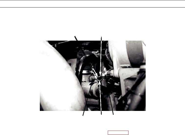
21.
Remove two screws (42), chassis wiring harness connector (43) (red wire), chassis wiring harness connector (44) (pur-
ple wire), and chassis wiring harness (30) from engine coolant temperature switch (45).
42
43
449-063
30
44
45
CLEANING AND INSPECTION
Clean and inspect all parts IAW General Maintenance Instructions (WP 0014 00).
INSTALLATION
NOTE
Install wires and wiring harness as tagged at removal.
During installation, route wiring harnesses as noted during removal.
1.
Install chassis wiring harness (30), chassis wiring harness connector (44) (purple wire), chassis wiring harness connec-
tor (43) (red wire), and two screws (42) on engine coolant temperature switch (45).
2.
Install diode assembly (39), diode connector (35), locknut (36), and bolt (37) on vehicle.
3.
Connect diode assembly connector (38) to compressor cable (34).
4.
Connect diode assembly connector (40) to chassis wiring harness (30).
5.
Install new tiedown straps (41) on chassis wiring harness (30) along A/C hoses to compressor.
0021 00-7

