
TB 9-2300-420-20-1
PARKING BRAKE CONTROL ASSEMBLY ADJUSTMENT - Continued
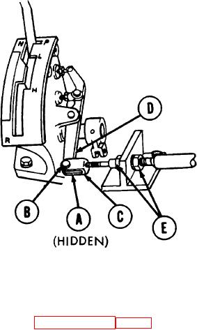
11. Place shift lever in P (park) position.
12. Aline clevis (C) with parking brake lever (D), by
adjusting nuts (E) with two 15/16 inch
combination wrenches. Install pin (B) and new
cotter pin (A).
13. Remove locating pin from bellcrank, installed in
step 5.
14. Check parking brake for normal operation.
NOTE
Upon completion of control assembly adjustment, proceed to INSPECTION III page 7.
END OF TASK
TA 173251
13

